
After much research on the safety of trying to connect an unbalanced 1/4″ jack (TS) to a balanced, phantom power enabled XLR input on my mixer using a simple interconnect adaptor, I decided that I should just invest in a DI (Direct Injection) box – which will solve the problem beyond any reasonable doubt.
Considering mixers have 1/4″ jacks (which support both balanced or unbalanced inputs) anyway, you may be thinking why go through all the trouble of trying to connect a naturally unbalanced instrument cable to a balanced input?[1]: http://www.taylorguitars.com/guitars/t5/soundcheck/ “Visit site”
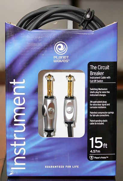
Firstly, AFAIK, [my guitar (T5)][1] supports both balanced and unbalanced cables – so it’s nice to have a provision in my setup for it. And balanced is always better as a rule (more on this later). Of course in my “home studio” environment, this is probably a moot point since I still have to used a regular mono 1/4″ jack from the guitar (since my cool “circuit-breaker” instrument cable is mono/unbalanced) anyways. Also, there’s not much to worry about when dealing with short distances.
Still, the boost in volume used with a balanced connection is very helpful for recording. As they say, the stronger your input source (as long as it ain’t clipping), the better.
Hold on… Balanced? Unbalanced? What the hell are you talking about?
This attempt to clarify the concept of balanced connections was also triggered by a discussion between Nono and I about different audio interconnects
Remember when you look at your regular 1/4″ jack (common for musical instruments) and sometimes you would see two black (or colored) rings, but never knew what the difference was with those jacks with one ring only? Same goes with those earphone jacks – which commonly have two as a standard.
These “rings” are dividers, and I will start calling them as such. 1 Because techincally, balanced jack plugs are called TRS (Tip-Ring-Sleeve) jacks – and obviously the word “ring” here pertains to the middle contact point, not the ring divider. In the headphone example, many of you might now be catching up as to why you have such divisions in that metal jack. It forms enough pathways for a stereo connection. The metal jack is divided by the two rings into three contact points: one ground and two others for the left and right channel. Connectors with one divider naturally form a mono connection: your ground and primary signal.
This stereo configuration is also called a balanced configuration – and conversely, mono connectors are unbalanced.
But in my opinion (as I haven’t researched enough about it), it is to note that a balanced connection doesn’t necessarily mean stereo. The purpose of balanced architecture was a means to interconnect communication devices over long distances (e.g. the telephone system) using regular, low quality wiring. So while telephones are assumed to be monaural (mono), they use balanced connections because of its ability to cancel out common-mode voltage. 2 Noise produced by extraneous ground voltage between the two interconnected devices.
Common-mode voltage is different from your regular EMI 3 ElectroMagnetic Interference as the latter is external, and can be suppressed depending on the quality of shielding your cables have. The common-mode currents (or ground-loop currents) that run through cables are an internal phenomenon – and are usually introduced by the interconnected devices themselves. Just for the sake of mentioning it, audio information running through wires is still ultimately electrical currents. So while a certain electrical current represents your audio data, the “noise” introduced by factors mentioned above will obviously distort that sound when the endpoint finally converts it all back to audio data.
Balanced systems solve this problem by using phase cancellation to to the resulting audio output. And I’ve prepared a diagram which will hopefully be clearer and simpler than what you can find on the net. I’ve also included a legend to relate it to a typical [balanced] XLR cable. And I have more notes on the picture on its Flickr page.

The first column represents the audio signal running through a balanced cable. The second and third represents the voodoo that happens to the signal when it reaches the input device. The last column is the theoretical resulting signal. This same example is also why I had to mention why a balanced connection doesn’t necessarily mean stereo – because you’ll see that you’re basically just dealing with one signal.
The concept of a balanced signal incorporates the technique of including a differential signal (blue) along with the primary (orange). This differential (cold) signal is basically the primary signal which is inverted, or what is called out-of-phase.
Now in the diagram, I’ve included the noise generated by common-mode voltage – which is running through each and every line. It will have the same characteristics regardless of the cold signal being the inverse of the primary. Remember, the noise is generated in the signal path, not the source. So while your source already flipped the cold signal, the common-mode voltage is constant starting from where the cable starts (not what the source spits out, capish?) Hence you’ll see the diagram having the exact same noise footprint regardless of what phase the signal is in.
Anyways, when you hook up to a device that supports balanced input (e.g. a mixer, etc.), it has the required circuitry to process these two, out-of-phase signals and do its magic. I threw in the ground in the diagram, but ultimately:
A grounded shield is still used to prevent high-frequency noise, and it might form a hum-gathering antenna – particularly if there are other ground connections. But since the ground isn’t part of the audio path, nobody cares.
So we go back to the two signals in question, where as you can see from the second column, it flips the differential signal. This results in the cold signal flipped back in-phase but since you have noise already in there, naturally that aspect, relative to the source signal, will now be out-of-phase.
The 3rd column shows how these two signals are now added together. The primary signal is now essentially doubled (since both are now in-phase) which results in a 6db boost, or twice the volume, which explains why the same stuff connected to balanced inputs are louder than when connected via unbalanced.
For the noise however, if we remember our audio basics, we know that opposing frequencies cancel each other out. Since your cold signal now has an opposing, out-of-phase noise footprint, we then leave it to the laws of physics to cancel your undesired noise out.
Now we know why telephone companies use the balanced architecure, and this preference still holds true for audio components in general.
For an unbalanced signal, just take out the cold part. So you’re left with the ground/shield and the primary signal. And as mentioned before, while the shielding can protect you from EMI, it can’t do shit for common-mode voltage. So if you choose to go unbalanced for all your stuff, some major grounding trickery will have to be applied should you start experiencing hardware hum.
Notes
| ⇡1 | Because techincally, balanced jack plugs are called TRS (Tip-Ring-Sleeve) jacks – and obviously the word “ring” here pertains to the middle contact point, not the ring divider. |
|---|---|
| ⇡2 | Noise produced by extraneous ground voltage between the two interconnected devices. |
| ⇡3 | ElectroMagnetic Interference |
Thanks for the explanation dude. Now I’m thinking if I should get both the FCA202 and a DI box. Sigh. =) Money, money, money! =)
That would be ideal 🙂 The next problem you’re going to have to deal with though is what type of DI box.
Mine has 1/4″ unbalanced input, and a balanced XLR out as well as a passthrough (which I think is mono as well … and it’s also 1/4″)
Since you mentioned the FCA202 only has 1/4″ inputs, then you have to make sure the DI box you get also has a 1/4″ TRS out, since mas common yung XLR out. Of course I guess you can always get a female XLR to male TRS adaptor for it.
After you’ve decided on that, next you’d have to worry about powering the thing. If you get an active box like mine, you’ll need a battery or phantom power (which is more common in XLR connectors). Since I’m sure the FCA202 doesn’t have phantom power to begin with (unless it states that it can actually give phantom power from a TRS jack, and assuming the DI box you get can take phantom power from such jacks) then that would mean you’ll have to use batteries all the time – or get a passive DI box.
Hahahaha, daming problemang nadagdag ano?
Dami nga problemang nadagdag. Thanks dude!